Engineering Drawings for BIS Certification
Engineering Drawings for BIS Certification: What Furniture Manufacturers Must Include
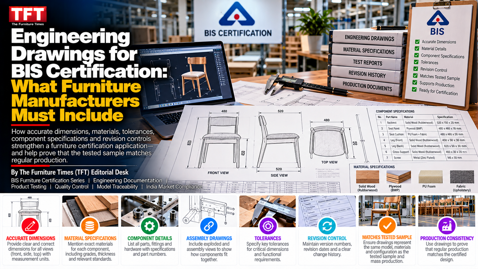
How accurate dimensions, materials, tolerances, component specifications and revision controls strengthen a furniture certification application—and help prove that the tested sample matches regular production
By The Furniture Times (TFT) Editorial Desk
BIS Furniture Certification Series | Engineering Documentation | Product Testing | Quality Control | Model Traceability | India Market Compliance
Furniture manufacturers often treat engineering drawings as internal production documents. Under a BIS certification programme, however, drawings can become critical evidence connecting five important elements:
- The model declared in the application
- The representative sample selected for testing
- The construction tested by the laboratory
- The product manufactured during regular production
- The models ultimately included within the licence scope
If these five elements do not match, even a well-performing furniture product can face questions, delays, repeat testing or restrictions on the certification scope.
A laboratory report may show that a chair, table, storage unit or bed passed the applicable tests. But the report alone may not establish precisely which frame, dimensions, joints, materials, mechanisms or components were tested.
That is where controlled engineering drawings become important.
A good drawing answers a simple but essential question:
What exactly is the certified product?
It identifies the product’s construction in a form that production teams, quality personnel, laboratories, inspectors and BIS officials can understand consistently.
As furniture certification under India’s Furniture Quality Control Order develops, manufacturers must move beyond catalogue photographs and marketing descriptions. They need a controlled technical record for every declared model and model family.
The Furniture Categories Covered by the BIS Framework
The Bureau of Indian Standards currently lists the following six furniture categories under the Furniture Quality Control Order and Scheme-I certification framework:
| Furniture category | Applicable Indian Standard |
|---|---|
| Work chairs | IS 17631:2022 |
| General-purpose chairs and stools | IS 17632:2022 |
| Tables and desks | IS 17633:2022 |
| Storage units | IS 17634:2022 |
| Beds | IS 17635:2022 |
| Bunk beds | IS 17636:2022 |
The Furniture Quality Control Order has also been subject to amendments and transition-related notifications. Manufacturers must therefore verify the latest QCO, amendment, applicable date, Indian Standard and product manual before filing or modifying an application.
The exact drawing and declaration requirements can differ according to:
- Product category
- Applicable Indian Standard
- Current product manual
- Model-grouping provisions
- Product construction
- Scope requested by the manufacturer
- Whether the application concerns grant or scope extension
- Clarifications requested during scrutiny or inspection
This article provides a practical engineering-documentation framework. It should be used with the latest official BIS documents and product-specific advice applicable to the manufacturer.
Why Engineering Drawings Matter in BIS Certification
1. Drawings establish the identity of the model
A model name alone is insufficient.
Names such as:
- Executive Chair
- Comfort 200
- Hotel Chair A
- Study Table
- Premium Bed
- Modular Storage Unit
do not explain how the product is constructed.
Two products may carry the same commercial name while using different:
- Bases
- Frames
- Armrests
- Backrest structures
- Tabletop materials
- Drawer mechanisms
- Fasteners
- Leg sections
- Bed-support systems
- Overall dimensions
The drawing gives the model a technical identity beyond its marketing name.
2. Drawings connect the sample with the test report
The product sent to a laboratory must correspond to the product declared in the application.
The drawing can help establish:
- Which model was sampled
- Which configuration was tested
- Whether it was fixed or adjustable
- Whether it had castors
- Whether an extension element was fitted
- Which frame and base were used
- Which dimensions applied
- Which materials and components formed the tested configuration
If a test report identifies only a broad product description while the application seeks multiple variants, reviewers may be unable to determine what the report actually covers.
3. Drawings help evaluate model families
Current furniture product manuals may allow models to be considered within families when prescribed parameters are common or remain within defined limits.
For example, the BIS grouping guidelines for tables and desks require manufacturers to declare their models with essential parameters and a drawing for each model. The listed considerations include principal material, construction, castors, extension elements, fixed or adjustable height and dimensions.
The current published grouping guidance also describes a model family using common performance category, material and construction, with relevant dimensions remaining within the specified range around the lead model.
A model-family proposal is therefore much easier to evaluate when drawings clearly identify similarities and differences.
4. Drawings support factory inspection
During an assessment, inspectors may need to compare:
- Application documents
- Raw materials
- Components in storage
- Work-in-progress products
- Finished products
- Quality-control records
- Test samples
- Declared models
Controlled drawings help the factory demonstrate that the product being manufactured is the declared construction.
5. Drawings support continued compliance
BIS certification is not only about obtaining a passing laboratory report. BIS states that licensing is based on assessment of manufacturing infrastructure, process controls, quality control and testing capabilities, together with evidence that the product conforms to the relevant standard.
After certification, drawings can serve as reference documents for:
- Incoming inspection
- In-process inspection
- Final inspection
- Supplier control
- Change approval
- Complaint investigation
- Internal testing
- Production consistency
- Surveillance preparation
A well-controlled drawing is therefore both an application document and a manufacturing-control document.
What a BIS-Ready Furniture Drawing Should Contain
There is no single universal drawing template for every furniture category. A work chair, bunk bed and storage cabinet have different safety-critical characteristics.
Nevertheless, every drawing package should provide several fundamental types of information.
1. Drawing Identification
Every drawing should carry a title block containing, at minimum:
- Manufacturer’s legal name
- Manufacturing-unit address or unit code
- Product category
- Model name
- Unique model number or code
- Drawing number
- Revision number
- Date of issue
- Drawing scale
- Units of measurement
- Sheet number
- Total number of sheets
- Prepared by
- Checked by
- Approved by
A strong title block might identify the document as:
General-Purpose Chair — Model GC-104 — General Assembly Drawing — Drawing No. GC-104-GA-01 — Revision 02
The same model code should appear consistently in:
- BIS application
- Model declaration
- Test request
- Laboratory report
- Bill of materials
- Technical data sheet
- Product label
- Internal production documents
- Packaging, where applicable
Even small inconsistencies can create uncertainty.
“GC104,” “GC-104,” “Chair 104” and “Model G104” may refer to the same item internally, but a reviewer should not be expected to make that assumption.
2. General Arrangement Drawing
The general arrangement drawing should show the complete product.
It should normally include appropriate views such as:
- Front view
- Side view
- Rear view
- Top view
- Bottom view, where relevant
- Isometric or three-dimensional view
- Sectional views
- Exploded view, where needed
Not every product requires every view. The purpose is to remove ambiguity.
A front photograph of a chair may not show how the backrest connects to the frame. A top view of a table may not reveal the underframe. A closed storage cabinet may hide the drawer runners, shelf supports and wall-anchoring arrangement.
The drawing set should make the construction understandable.
3. Overall Dimensions
The product’s overall dimensions should be clearly stated in millimetres unless another unit is specifically required.
Typical dimensions include:
- Overall width
- Overall depth
- Overall height
- Seat height
- Seat width and depth
- Backrest height and width
- Armrest height and spacing
- Tabletop height, width and length
- Clearance beneath a desk
- Storage-unit height, width and depth
- Internal shelf dimensions
- Bed length and width
- Mattress-support height
- Bunk-bed clearances
- Guardrail height
- Ladder width and inclination
The manufacturer should identify which dimensions are:
- Fixed
- Adjustable
- Nominal
- Minimum
- Maximum
- Dependent on product configuration
For an adjustable work chair, stating only one total height may be misleading. The drawing should show the adjustment range.
For an extendable table, both closed and fully extended dimensions should be declared.
For a modular storage unit, each configuration should be distinguishable.
4. Functional and Safety-Critical Dimensions
Overall dimensions are not enough.
Furniture drawings should identify dimensions that may affect:
- Stability
- Strength
- Durability
- Entrapment risk
- Shear and pinch points
- Clearances
- User access
- Load transfer
- Guarding
- Support
- Tip-over behaviour
Examples include:
Chairs
- Seat height
- Effective seat depth
- Backrest position
- Armrest spacing
- Chair-base diameter
- Castor spacing
- Frame-tube dimensions
- Leg angles
- Position of structural joints
- Adjustment limits
Tables and desks
- Top height
- Clearance beneath the top
- Overhang
- Leg spacing
- Support-frame position
- Base footprint
- Extension length
- Adjustable-height limits
- Castor location
Storage units
- Unit height-to-depth relationship
- Base footprint
- Drawer projection
- Shelf spans
- Door dimensions
- Wall-anchoring positions
- Internal support locations
- Castor placement
- Load-bearing member dimensions
Beds
- Internal mattress dimensions
- Side-rail dimensions
- Support spacing
- Leg positions
- Centre-support arrangement
- Headboard and footboard construction
- Ground clearance
- Joint positions
Bunk beds
- Guardrail dimensions
- Gaps and openings
- Distance between sleeping surfaces
- Ladder dimensions
- Access opening
- Mattress reference line
- Maximum mattress thickness indicator
- Structural-member sizes
- Guardrail attachment points
A dimension should not be omitted merely because the production team “already knows it.”
Certification documentation must remain understandable to people outside the production department.
5. Material Identification
The drawing should identify the principal material of every structural component.
Generic descriptions such as “wood,” “metal,” “board” or “plastic” are usually too vague for proper technical control.
Depending on the product, the drawing or linked specification should identify:
- Solid-wood species or approved material specification
- Engineered-wood type
- Board thickness
- Plywood grade
- Particleboard or fibreboard specification
- Steel grade
- Aluminium grade
- Tube dimensions and wall thickness
- Plastic or polymer type
- Reinforcement material
- Glass type and thickness
- Upholstery-support material
- Foam type or density, where relevant
- Fabric, leather or coated material
- Adhesive system
- Surface coating or finish
For example:
Weak description:
Metal leg
Stronger description:
Powder-coated mild-steel rectangular tube, 30 × 20 × 1.5 mm
Similarly:
Weak description:
Wooden tabletop
Stronger description:
25 mm engineered-wood panel with specified surface laminate and protected edges
The actual specification must reflect the approved construction. Manufacturers should not insert impressive-looking material details that are not controlled or verified in production.
6. Component Specifications
Every major component should have a unique item number connected to the bill of materials.
A work-chair drawing may identify:
- Seat pan
- Backrest frame
- Armrest
- Gas-lift column
- Tilt mechanism
- Five-star base
- Castors
- Seat cushion
- Back cushion
- Fasteners
A storage-unit drawing may identify:
- Side panels
- Top and bottom panels
- Back panel
- Shelves
- Doors
- Hinges
- Drawer runners
- Handles
- Locks
- Levelling feet
- Wall anchors
- Fasteners
The component record should state, where relevant:
- Part number
- Component description
- Material
- Key dimensions
- Quantity per product
- Supplier or approved supplier code
- Performance rating
- Surface finish
- Applicable component drawing
- Inspection requirement
The drawing and bill of materials must agree.
If the drawing identifies a five-star nylon chair base but the bill of materials lists an aluminium base, the application contains a fundamental inconsistency.
7. Section Sizes and Thicknesses
Structural performance frequently depends on details hidden by the finished product.
The drawing should identify relevant:
- Tube diameter
- Tube wall thickness
- Wood-member cross-section
- Panel thickness
- Sheet thickness
- Plate thickness
- Glass thickness
- Bracket thickness
- Edge-band thickness
- Support-rail dimensions
- Guardrail dimensions
A bed using 30 mm side rails and another using 18 mm side rails may look similar in a catalogue image but perform differently under testing.
Likewise, two tables with identical external dimensions may use entirely different underframes.
These differences matter when deciding whether one tested sample can reasonably represent another model.
8. Joints and Connection Details
Furniture often fails at connections rather than in the middle of a component.
Drawings should show how structural parts are joined, including:
- Welds
- Bolts
- Screws
- Rivets
- Dowels
- Cam-and-dowel fittings
- Mortise-and-tenon joints
- Corner blocks
- Brackets
- Adhesive joints
- Knock-down connectors
- Clips
- Hooks
- Interlocking fittings
The drawing should identify important details such as:
- Fastener diameter and length
- Fastener grade or specification
- Number of fasteners
- Hole positions
- Edge distances
- Weld location and type
- Weld length
- Adhesive application area
- Insert type
- Tightening requirement
- Reinforcement arrangement
“Joined securely” is not an engineering specification.
If the tested sample contains four bolts but normal production uses two, the certified result may not represent the production model.
9. Mechanisms and Moving Parts
Adjustable and convertible furniture requires additional documentation.
The drawing package should identify mechanisms such as:
- Gas lifts
- Tilt mechanisms
- Reclining mechanisms
- Height-adjustment systems
- Manual cranks
- Electric actuators
- Table-extension systems
- Folding mechanisms
- Swivel mechanisms
- Drawer runners
- Hinges
- Locks
- Sliding-door hardware
- Sofa-bed mechanisms
- Castors and brakes
The documents should show:
- Mechanism model or part number
- Adjustment range
- Mounting arrangement
- Operating direction
- Locking positions
- Load rating, where controlled
- Electrical details, where applicable
- Safety stops or guards
- Supplier specification reference
Replacing a mechanism after testing may create a new technical configuration, even when the outward appearance remains unchanged.
10. Tolerances
Furniture drawings frequently contain nominal dimensions but no tolerances.
That creates a serious production-control weakness.
If a table leg is shown as 700 mm long, can production accept 699 mm? What about 695 mm? What about 685 mm?
Without a declared tolerance, the drawing does not define the acceptable product.
Tolerances may be established through:
- General drawing tolerances
- Individual dimensional tolerances
- Material-thickness tolerances
- Hole-position tolerances
- Angular tolerances
- Fit and clearance requirements
- Flatness or alignment requirements
- Mechanism-adjustment limits
A drawing may state:
Unless otherwise specified, linear dimensions ±2 mm and angular dimensions ±1°
However, a general tolerance should not be used indiscriminately. Safety-critical or functional dimensions may require tighter or specifically defined limits.
Manufacturers should ensure that tolerances:
- Are technically achievable
- Match production capability
- Do not permit non-conforming safety dimensions
- Are checked using available measuring equipment
- Correspond with the Indian Standard where the standard prescribes limits
A factory should never invent tolerances only for the application. The declared tolerances should form part of regular production control.
11. Surface Finishes and Treatments
Surface-performance testing may be relevant to furniture covered by the applicable standard.
The technical file should therefore identify, where applicable:
- Paint system
- Powder-coating system
- Plating
- Anodising
- Laminate
- Veneer
- Lacquer
- Stain
- Sealer
- Edge treatment
- Upholstery material
- Corrosion-protection process
- Coating colour or finish code, when technically relevant
If several colours use the same coating chemistry and process, this should be documented.
If changing the colour also changes the coating supplier, formulation, application method or curing process, the manufacturer should evaluate whether the variation affects declared performance or certification evidence.
A decorative difference is not always merely decorative.
12. Load Ratings and Intended Use
The drawing or technical data sheet should identify the product’s intended use and performance category where applicable.
Examples include:
- Office work chair
- Domestic chair
- Outdoor stool
- Office desk
- Domestic study table
- Storage cabinet
- Adult bed
- Bunk bed
Avoid printing unsupported load capacities on drawings or marketing documents.
If a manufacturer declares a load rating, it should understand:
- How the value was determined
- Whether the applicable standard supports that declaration
- Whether the test conditions correspond to actual use
- Whether the rating applies to every model variant
A tested proof load is not automatically the same as a recommended maximum user load.
13. Assembly Information
Ready-to-assemble furniture requires especially clear documentation.
The package should include:
- Exploded assembly view
- Component identification
- Hardware list
- Assembly sequence
- Required tools
- Fastener locations
- Tightening instructions
- Orientation of components
- Safety warnings
- Wall-anchoring instructions, where applicable
- Maximum mattress information for bunk beds, where relevant
- Post-assembly inspection points
The product manual for tables and desks confirms that the standard covers both completely manufactured or fabricated products and ready-to-assemble units.
The tested sample must be assembled using the same components and method intended for the market.
An experienced laboratory technician may be able to assemble a vague sample correctly, while an ordinary consumer may not. Poor assembly instructions can therefore create real-world safety and consistency problems.
14. Bill of Materials Linkage
The engineering drawing and bill of materials should form one controlled system.
A recommended bill-of-material structure includes:
| Item | Part number | Description | Material/specification | Key dimension | Quantity | Drawing reference |
|---|---|---|---|---|---|---|
| 01 | CH-210-01 | Seat frame | Steel tube | 25 × 25 × 1.5 mm | 1 | CH-210-C01 |
| 02 | CH-210-02 | Front leg | Steel tube | 25 × 1.5 mm | 2 | CH-210-C02 |
| 03 | CH-210-03 | Seat panel | Plywood | 12 mm | 1 | CH-210-C03 |
| 04 | HW-M6-35 | Assembly bolt | Approved specification | M6 × 35 mm | 4 | Hardware specification |
| 05 | CH-210-05 | Backrest | Moulded polymer | Model-specific | 1 | CH-210-C05 |
The identifiers used in the bill of materials should match the callouts in the assembly drawing.
A separate approved-supplier list can then identify where controlled components may be sourced.
15. Model and Variant Matrix
Where an application contains multiple models, the drawing package should include a comparison matrix.
| Parameter | Model A | Model B | Model C |
|---|---|---|---|
| Frame material | Steel | Steel | Aluminium |
| Seat material | Plywood | Moulded plastic | Plywood |
| Armrests | None | Fixed | Adjustable |
| Base | Four-leg | Sled | Five-star |
| Castors | No | No | Yes |
| Height adjustment | No | No | Gas lift |
| Overall width | 480 mm | 510 mm | 640 mm |
| Drawing revision | R02 | R01 | R03 |
| Proposed family | Family 1 | Family 2 | Family 3 |
| Test status | Tested | To be evaluated | Tested |
This prevents visual similarity from being mistaken for technical equivalence.
A change from a four-leg base to a pedestal base is not simply a styling change. It changes stability and load distribution.
A change from fixed to adjustable arms may introduce new joints and failure modes.
A change in tabletop size can affect stability, deflection and strength.
Every variant should therefore be assessed against the current BIS grouping requirements.
Understanding Lead Models and Model Families
A manufacturer may have dozens or hundreds of SKUs. Testing every colour or minor decorative variation separately may be unnecessary—but assuming that one sample covers an entire catalogue is equally dangerous.
The model-family process should begin with engineering comparison.
Models proposed within one family should be evaluated for differences in:
- Performance category
- Principal material
- Construction
- Dimensions
- Structural sections
- Mechanisms
- Adjustment features
- Extension elements
- Castors
- Joints
- Load-bearing components
- Safety-critical openings
- Stability geometry
The representative or lead model should be selected using the applicable grouping guidelines—not merely because it is the best-selling or easiest product to send to the laboratory.
For tables and desks, the current BIS grouping document identifies specific family parameters and relevant dimensional considerations.
For work chairs and other furniture categories, manufacturers must consult the current product-specific manual because grouping provisions can be revised.
Drawing Revision Control: The Most Overlooked Requirement
Furniture designs change constantly.
A manufacturer may:
- Replace a discontinued hinge
- Reduce a tube thickness
- Change a supplier
- Modify the seat width
- Add a reinforcement bracket
- Change a castor
- Use a new gas lift
- Modify a weld
- Change a panel material
- Increase a tabletop size
- Introduce a different base
- Revise a bunk-bed guardrail
Without revision control, the business may lose track of which construction was tested and certified.
Every controlled drawing should show
- Current revision number
- Revision date
- Description of change
- Person who prepared the change
- Person who reviewed it
- Person who approved it
- Effective production date
- Models affected
- Assessment of certification impact
A revision table may look like this:
| Revision | Date | Change | Certification impact | Approval |
|---|---|---|---|---|
| R00 | 10 Jan 2026 | Initial issue | Initial BIS application | Approved |
| R01 | 15 Mar 2026 | Hole position corrected | No structural change; document correction | Approved |
| R02 | 12 Jul 2026 | Tube wall changed from 1.5 to 1.2 mm | Technical review and BIS impact assessment required | Pending |
Not every revision has the same significance
Changes can be classified as:
Administrative change
Examples:
- Spelling correction
- Updated company address
- Improved drawing clarity
- Renumbered note
Minor technical change
Examples may include:
- Non-structural colour change
- Decorative stitching
- Packaging change
- Equivalent label position
Major technical change
Examples include:
- Material substitution
- Reduced thickness
- New base
- Different mechanism
- Altered structural dimensions
- Different joint
- New armrest configuration
- Added castors
- Increased load-bearing span
- Modified guardrail or ladder
The manufacturer should not independently assume that a change is covered by the existing licence. Its quality and regulatory team should evaluate the current licence scope, standard, product manual and BIS requirements before implementing the change.
The “Golden Sample” and Drawing Connection
A retained reference sample can help the factory preserve product identity.
Where practical, the manufacturer should maintain:
- Approved drawing
- Approved bill of materials
- Photographs of the tested sample
- Test report
- Sample identification record
- Component certificates
- Inspection results
- Approved production sample or controlled reference components
The golden-sample system is especially useful when the tested product contains components whose detailed construction is difficult to show in a single drawing.
Photographs should capture:
- Full product
- Model label
- Bottom or rear construction
- Joints
- Mechanisms
- Base
- Castors
- Structural supports
- Hardware
- Sample-sealing information, where applicable
Photographs are useful supporting records, but they should not replace dimensioned engineering drawings.
Frequent Drawing Mistakes That Delay Applications
1. Submitting a catalogue image instead of a technical drawing
A catalogue image shows appearance. It usually does not establish materials, construction, dimensions or joints.
2. Using the same drawing for several structurally different models
Products with different bases, frames, mechanisms or materials should not be represented by one generic drawing unless the differences are clearly controlled through variant drawings and the grouping rules support the proposed family.
3. Omitting material thicknesses
“Steel frame” does not identify tube size or wall thickness.
4. Declaring dimensions without tolerances
A nominal dimension alone does not define the acceptable manufactured range.
5. Inconsistency between drawings and the bill of materials
If the drawing, BOM and sample disagree, the technical file becomes unreliable.
6. Different model numbers across documents
A laboratory report for “CH-201” cannot automatically be connected to an application for “Chair Model 201A.”
7. Failing to show adjustment ranges
Height-adjustable or extendable furniture must be documented in its relevant configurations.
8. Missing revision numbers
Without a revision, nobody can determine which drawing controlled the tested sample.
9. Revising production without reviewing certification impact
A purchasing substitution can unintentionally create an uncertified variant.
10. Drawings do not reflect actual factory production
A perfectly formatted drawing is useless if employees manufacture from verbal instructions or an outdated shop-floor sketch.
11. Undeclared imported components
Gas lifts, mechanisms, castors, hinges or runners should be traceable to the specification used in the declared product.
12. Excessive detail without document control
A drawing package containing hundreds of uncontrolled pages can create as much confusion as an incomplete submission.
The objective is complete, relevant and controlled information.
Departmental Responsibility Must Be Clear
BIS documentation should not be left entirely to one employee or outside consultant.
A coordinated process is needed.
| Department | Responsibility |
|---|---|
| Design/engineering | Prepare drawings, specifications and revision records |
| Production | Confirm that drawings match actual manufacturing |
| Purchasing | Control approved materials, components and suppliers |
| Quality assurance | Verify dimensions, materials and production conformity |
| Laboratory/testing team | Match samples and reports to model identifiers |
| Regulatory/BIS coordinator | Align the technical file with the application and licence scope |
| Senior management | Approve resources and prevent uncontrolled substitutions |
An outside consultant may help organise the application, but only the manufacturer can reliably confirm what is produced inside the factory.
Certification cannot be outsourced completely.
A Practical Pre-Submission Drawing Checklist
Before submitting a furniture model for BIS certification, verify the following.
Document identity
- Is the model number unique?
- Does it match the application and BOM?
- Is the drawing number shown?
- Is the current revision identified?
- Are the date and approvals recorded?
- Are units and scale stated?
Product definition
- Are sufficient views provided?
- Are overall dimensions shown?
- Are functional dimensions included?
- Are adjustable ranges declared?
- Are safety-critical clearances identified?
- Are applicable tolerances stated?
Materials and construction
- Are principal materials identified?
- Are panel and tube thicknesses stated?
- Are structural sections defined?
- Are joints and fasteners shown?
- Are mechanisms identified?
- Are surface finishes controlled?
Variant control
- Does every declared model have a drawing?
- Are model differences clearly identified?
- Is a comparison matrix available?
- Is the proposed family supported by current grouping guidelines?
- Is the lead model clearly identified?
- Does the tested configuration represent the declared scope?
Production consistency
- Does the drawing match the physical sample?
- Does the BOM match the drawing?
- Does the factory manufacture to the same revision?
- Are measuring instruments available to verify declared dimensions?
- Are component substitutions controlled?
- Are obsolete drawings removed from the production floor?
Laboratory alignment
- Is the exact model number stated in the test request?
- Is the drawing revision recorded?
- Are sample photographs retained?
- Does the laboratory report describe the tested configuration sufficiently?
- Can the test report be unambiguously linked to the drawing?
Recommended Technical Drawing Package
A strong application file may contain:
- Drawing register
- General assembly drawing
- Dimensioned orthographic views
- Exploded assembly drawing
- Structural-detail drawings
- Joint and fastener details
- Mechanism specifications
- Bill of materials
- Approved-component specifications
- Model and variant matrix
- Lead-model declaration
- Product photographs
- Assembly instructions
- User and safety instructions
- Revision history
- Drawing-approval records
- Test-sample identification sheet
- Change-control procedure
Not every application will require every item in the same form. The package should remain proportionate to product complexity and aligned with current BIS requirements.
Drawings Should Control Production—Not Merely Satisfy the Application
Some factories create professional drawings shortly before inspection but continue manufacturing through:
- Verbal instructions
- Old samples
- Informal workshop notes
- Supplier recommendations
- Uncontrolled messaging-app photographs
- Outdated cutting lists
This creates a dangerous divide between the certification file and the actual product.
A BIS-ready system should ensure that:
- The current drawing is available at the relevant workstation
- Obsolete revisions are withdrawn
- Production changes require approval
- Incoming components are checked against specifications
- Critical dimensions are measured and recorded
- Final inspection refers to the approved model definition
- Non-conforming products are controlled
- Supplier changes trigger technical review
The drawing should represent the product being made every day—not an idealised version prepared for an inspection.
The Central Compliance Principle
An engineering drawing does not make furniture compliant by itself.
It does something equally important: it defines the product whose compliance must be demonstrated.
The drawing strengthens traceability from:
Declared model → selected sample → laboratory testing → licence scope → regular production
If any link breaks, certification confidence weakens.
Manufacturers should therefore stop treating drawings as decorative attachments. They are part of the technical foundation of the application and, when properly controlled, of the entire manufacturing system.
The most important question is not:
Do we have a drawing?
It is:
Does the approved drawing accurately define the product we tested, declared and manufacture?
If the answer is yes, the certification application becomes clearer, model grouping becomes easier to justify, inspections become more efficient and production changes become easier to control.
If the answer is no, even a passing test report may not resolve uncertainty about the certification scope.
A Final Advisory to Furniture Manufacturers
Before filing an application:
- Obtain the latest applicable Indian Standard
- Review the current product manual
- Confirm the latest QCO and amendments
- Finalise the product configuration
- Assign unique model numbers
- Prepare controlled drawings
- Align drawings with the BOM
- Declare every relevant variant
- Select the representative sample correctly
- Freeze the test-sample revision
- Preserve photographs and sample records
- Introduce formal engineering-change control
Do not send a model for testing while its design is still changing.
Do not use catalogue names as a substitute for technical identity.
Do not assume a change is minor merely because customers cannot see it.
Do not allow purchasing teams to substitute structural components without regulatory review.
The drawing is the manufacturer’s technical promise: this is the product, this is how it is constructed and this is the configuration for which conformity is being demonstrated.
Important Regulatory Note
This article provides general industry guidance and is not a substitute for the applicable Indian Standard, current BIS product manual, QCO notification, official BIS direction or professional certification advice. Requirements and implementation arrangements may change. Manufacturers should verify the latest documents through BIS and the relevant Government of India authority before making certification decisions.
Sources:
Bureau of Indian Standards—Scheme-I Compulsory Certification Products, Bureau of Indian Standards—Apply for a Licence, BIS Product Manual and Grouping Guidelines for Tables and Desks, IS 17633:2022, BIS Product Manuals